- New
- Sale
- Temperature
- Humidity
- Pressure
- Light Intensity & Motion
- Air Quality
- Flow
- Modbus | Wireless Modbus
- Rymaskon
- EtherCAT P
- Accessory
Description
Vane switch / vane relay switch
RHEASREG® WFS
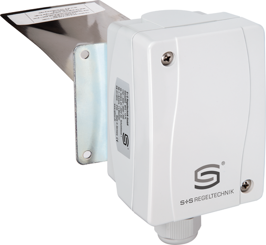
Mechanical wind vane switch RHEASREG® WFS wind vane switch with switching output, in an impact resistant plastic housing, with stainless-steel paddle, for flow monitoring of gaseous, non-aggressive media.
The flow sensor device is used as a flow controller or air flow monitor in air conditioning ducts, in air intake or exhaust devices of ventilators or in electric heating registers (also for contaminated, oily air).
Technical details
Switching capacity (Contact load)
15 (8) A; 24…250 V ACat 24 V AC min. 150 mA
Operating difference
1 m/ s
Contact
dust-proof micro switch
as single-pole potential-free changeover contact
as single-pole potential-free changeover contact
Operating medium
gaseous, non-aggressive media (also for polluted, oily air)
Control range
Switch-on value (min./max.): 2.5m/s / 9.2m/s
Switch-off value (min./max.): 1.0m/s / 8m/s
Switch-off value (min./max.): 1.0m/s / 8m/s
Electrical connection
AWG 16 - 26 via terminal screws
Cable connection
cable gland, plastic (M 16 x 1.5; with strain relief, exchangeable, max. inner diameter 0.4 in) or
M12 connector according to DIN EN 61076-2-101 (optional on request)
M12 connector according to DIN EN 61076-2-101 (optional on request)
Housing
plastic, UV-stabilised,
material polyamide, 30 % glass-globe-reinforced,
colour traffic white (similar to RAL 9016)
material polyamide, 30 % glass-globe-reinforced,
colour traffic white (similar to RAL 9016)
Base body
galvanised steel
Moving arm
brass
Vane
stainless steel, 1.4303, V2A
Screwed socket
-
Paddle
Stainless steel paddle cut to size
Housing dimensions
4.25 x 2.76 x 2.89 in (Thor 2)
Enclosure temperature
-40...+185 °F
Cable gland
M 20 x 1.5; including strain relief
Dimensions
4.25 x 2.76 x 2.89 in (Thor 2)
Protection class
I (according to EN 60 730)
Protection type
IP 65 (according to EN 60 529)*
Protection type housing
IP 65
Standards
CE conformity,
EMC directive 2014/ 30/ EU,
low-voltage directive 2014/ 35/ EU
EMC directive 2014/ 30/ EU,
low-voltage directive 2014/ 35/ EU
Function
Monitor: Contact 1 - 3 breaks when flow rate drops
to the preset value.
Simultaneously, contact 1 - 2 closes and
can be used as signal contact.
Device is factory-set to the minimum switch-off
value, which can be increased by turning the range
adjusting screw clockwise. Installation: vertical in horizontal air ducts.
Min. smoothing distance = 5 x duct diameter
upstream and downstream of vane. For airspeeds
> 5 m/ s, vane is to be trimmed at the marked
spots. Thereby the minimum switch-off value
increases to approx. 2.5 m/ s and the minimum
switch-on value to approx. 4 m/ s.


