- % SALE %
- Temperature
- Humidity
- Pressure
- Light Intensity & Motion
- Air Quality & Flow
- Modbus | Wireless Modbus
- PowerIO®
- EtherCAT P
- Accessory
Description
On-wall hygrostats
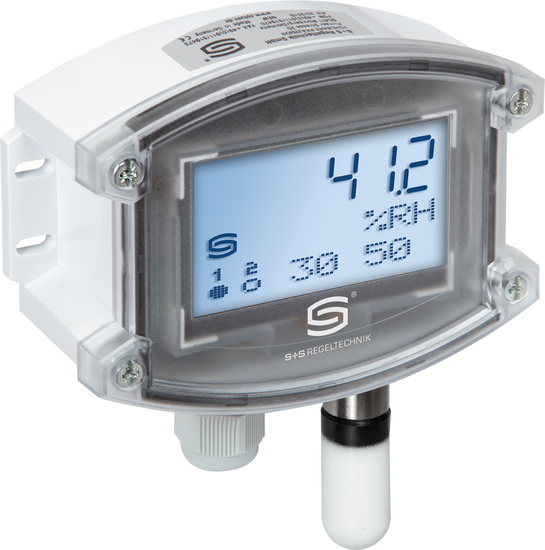
HYGRASREG® AHT-30
Electronic HYGRASREG® AHT-30 room hygrostat and/or room thermostat with one continuous and two switching outputs, adjustable switching thresholds, with/without optional display for indicating actual humidity and/or actual temperature (accuracy class ±2.0% r.H.). The setpoints can be allocated to relative humidity and/or temperature.
The measuring transducer serves to control and monitor relative humidity (humidifying and dehumidifying) and/or temperature (heating and cooling systems) e.g. in ventilation and air conditioning ducts, laboratories, production facilities, climate test chambers, indoor swimming pools, greenhouses, etc. It has been designed for precise humidity/temperature measurement. The RHT-30 uses a digital, long-term stable sensor as a measuring element. It is used in dust-free, unpolluted, non-aggressive air.
Technical details
Voltage supply
24 V AC/ DC (± 20 %)
Power consumption
< 1.5 VA/ 24 V DC, < 3.5 VA/ 24 V AC
Deviation of humidity
typical ± 2.0 % (20…80 % RH); at + 25 °C, otherwise ± 3.0 %
Temperature deviation
typically ± 0.4 K at +25 °C
Sensor
digital humidity sensor
with integrated temperature sensor,
low hysteresis, high long-term stability
with integrated temperature sensor,
low hysteresis, high long-term stability
Sensor protection
plastic sinter filter, Ø 16 mm, L = 35 mm, exchangeable
(optional metal sinter filter, Ø 16 mm, L = 32 mm)
(optional metal sinter filter, Ø 16 mm, L = 32 mm)
Operating difference
Mode 1: both switch steps are freely adjustable (rel. humidity)
Mode 2: 5 % between both switch steps (rel. humidity)
Mode 3: both switch steps freely adjustable (temperature)
Mode 4: switch step 1 (temperature), switch step 2 (rel. humidity)
(adjustable via DiP switches)
Mode 2: 5 % between both switch steps (rel. humidity)
Mode 3: both switch steps freely adjustable (temperature)
Mode 4: switch step 1 (temperature), switch step 2 (rel. humidity)
(adjustable via DiP switches)
Setting range
5...95 % r.H. (humidity)
Multi-range switching with
4 switchable measuring ranges
–35...+35 °C; –35...+75 °C; 0...+50 °C; 0...+80 °C (temperature)
(Switch steps 1 and 2 are separately adjustable)
Multi-range switching with
4 switchable measuring ranges
–35...+35 °C; –35...+75 °C; 0...+50 °C; 0...+80 °C (temperature)
(Switch steps 1 and 2 are separately adjustable)
Ambient temperature
storage –35...+85 °C;
operation – 30...+75 °C, non-precipitating
operation – 30...+75 °C, non-precipitating
Protective tube
stainless steel V2A (1.4301), Ø 16 mm, NL = 55 mm
Electrical connection
0.14 - 1.5 mm² via terminal screws
Cable connection
cable gland, plastic (M 16 x 1.5; with strain relief, exchangeable, max. inner diameter 10.4 mm) or
M12 connector according to DIN EN 61076-2-101 (optional on request)
M12 connector according to DIN EN 61076-2-101 (optional on request)
Housing
plastic, UV-stabilised,
material polyamide, 30 % glass-globe reinforced,
with quick-locking screws
(slotted/ Phillips head - combination),
colour traffic white (similar to RAL 9016),
housing cover for display is transparent !
material polyamide, 30 % glass-globe reinforced,
with quick-locking screws
(slotted/ Phillips head - combination),
colour traffic white (similar to RAL 9016),
housing cover for display is transparent !
Housing dimensions
126 x 90 x 50 mm (Tyr 2)
Cable gland
M 16 x 1.5, including strain relief, exchangeable,
max. inner diameter 10.4 mm
max. inner diameter 10.4 mm
Long-term stability
± 1 % per year
Protection class
III (according to EN 60 730)
Protection type
IP 65 (according to EN 60 529) housing only!
Standards
CE conformity, EMC directive 2014/ 30/ EU
Display
three-line display with illumination, cutout approx. 70 x 40 mm (W x H),
for displaying ACTUAL humidity and/or ACTUAL temperature
or for setpoint adjustment
for displaying ACTUAL humidity and/or ACTUAL temperature
or for setpoint adjustment
Function
Humidifying/heating:1st step: wire contacts 11 - 12.
If actual humidity falls more than 3 % r.H. / 1 K (hysteresis) below
switching threshold S1, the changeover contact switches to 11 - 12. 2. step: wire contacts 21 - 22.
If actual humidity falls more than 3 % r.H. / 1 K (hysteresis) below
switching threshold S2, the changeover contact switches to 21 - 22.
Terminal 2: output relative humidity / temperatureDehumidifying/cooling:1st step: wire contacts 11 - 13.
When actual humidity exceeds switching threshold S1,
the changeover contact switches to 11 - 13. 2. step: wire contacts 21 - 23.
When actual humidity exceeds switching threshold S 2,
the changeover contact switches to 21 - 23.
Terminal 2: output relative humidity / temperature
If actual humidity falls more than 3 % r.H. / 1 K (hysteresis) below
switching threshold S1, the changeover contact switches to 11 - 12. 2. step: wire contacts 21 - 22.
If actual humidity falls more than 3 % r.H. / 1 K (hysteresis) below
switching threshold S2, the changeover contact switches to 21 - 22.
Terminal 2: output relative humidity / temperatureDehumidifying/cooling:1st step: wire contacts 11 - 13.
When actual humidity exceeds switching threshold S1,
the changeover contact switches to 11 - 13. 2. step: wire contacts 21 - 23.
When actual humidity exceeds switching threshold S 2,
the changeover contact switches to 21 - 23.
Terminal 2: output relative humidity / temperature


